 You will probably have to use the shift key to stop the close spline points snapping together.
Mike10's fine scale turnouts were introduced with Trainz UTC. Immediately we could lay track that not only looked great, but was easy to use and worked very well. Using brilliant lateral thinking, Mike created the turnouts as level crossing objects (kind mocrossing) which gave a static object attachment points for track. You could connect standard track to each end of the crossing object, and never know that underneath was a junction made with invisible track. The crowning glory was an animated "point lever" made up to look like a motor and point blades. Add the "lever", and watch the points change direction when you clicked on them!
Many creators made substantial investments of time and effort making layouts which used Mike10's track and points extensively. It is not an exaggeration to say that this track and pointwork added a completely new dimension of realism to the operation of Trainz.
It became apparent at a very early stage of beta testing Trainz TRS that the code no longer coped with this method of making junctions. Despite numerous impassioned pleas from some beta testers, time could not be devoted to fixing whatever it was within Trainz that broke the support for these turnouts. Auran promised to look into the matter but it was obvious that nothing was going to happen quickly.
This became an increasingly sore point with me and was one of the major reasons I quit the beta testing and third-party creator programmes at the end of last year. I felt as though Auran were making a grievous error in not providing support to the serious end of the Trainz simming fraternity. At the time the Auranites were spread pretty thinly and there simply wasn't the available time or people to look at it; regardless of how important I and others considered the issue, it did not get high enough up the priority list to make it into TRS, SP1 or SP2 - even though the wooden toy track turnouts included with TRS were similarly broken.
Having left the beta programme I no longer felt compelled to toe the party line and made some rather inflammatory posts bolstering my own position and pointedly questioning Auran's.
I accepted Auran's offer to become involved in preliminary testing of SP2 and, among much other testing, confirmed that the mocrossing style turnouts were still broken.
Further investigation and testing of the behaviour of the objects in TRS revealed some possibilities that I had not been aware of. Correspondence with Mike10 and editing meshes in Gmax looked extremely positive; we could come up with some mesh changes that would make them compatible with TRS. I then looked further at what I had done and through some more lateral thinking proved that by ignoring the mocrossing aspects of the turnouts and treating them simply as scenery objects, we could get them to work in TRS.
Having confirmed and demonstrated this, the only honourable thing I could do was ring Tony Hilliam and offer my personal apology for some of the things I'd said, and undertake to write this tutorial so everyone could start using the turnouts in TRS.
Right now, I have developed a method of laying track which uses standard UTC Mike10 components. The job will be made much easier by development of a range of templates - lay the template, run the track up to points indicated on the template, delete the template and add the turnout. Alternatively, we may still progress down the path of editing the turnout meshes and reconfiguring them either as mocrossings or scenery objects. That's all in the near future - right now, this is how to do it manually.
Run ordinary spline track up to roughly where you want the turnout to be. I have used Mike10's Finescale 4m track for the example.
You will probably have to use the shift key to stop the close spline points snapping together.
Extend the end of the single track a little bit.
Using Mike10's Invisible Test Track, connect the straight parts and then make a junction midway with the curved part.
Delete the junction lever and replace with the appropriate Mike10 lever, in this case "MB Blades 10 Right". Ensure it is facing the correct way (you may have to rotate the lever) and set it towards the single track, using the move object, about halfway along the blades.
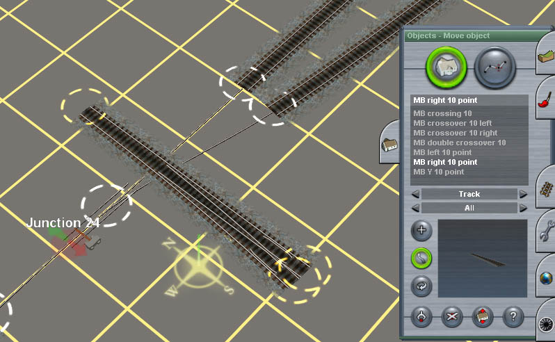
Place the MB Right 10 Point near the turnout. Anywhere will do, you'll need to rotate and move it. It's in the Buildings tab, under Track.
Now rotate it so that the straight lines up with the previously laid track. Position the turnout with the toe carefully butted up against the single track.
Move the spline points of the far tracks to the heel end of the turnout. I have left slight gaps to show the rail ends - don't do that, butt them up so that there is no visible join.


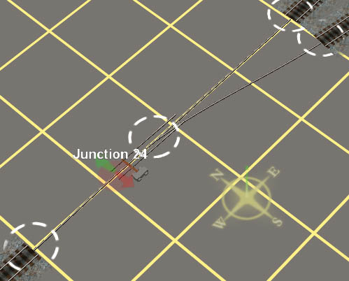
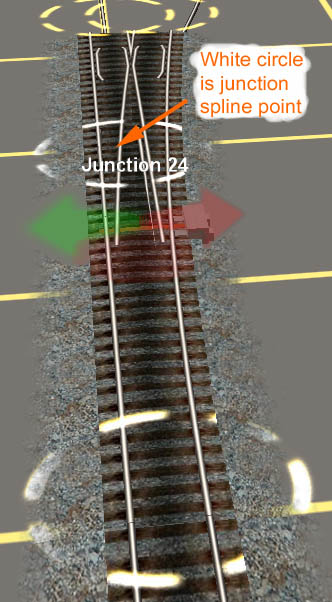
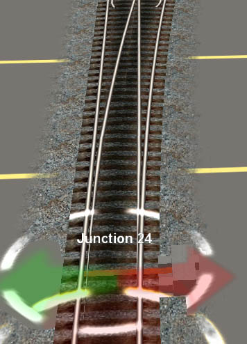
Now move the junction spline point (NOT THE POINT MOTOR/BLADES!) back so that the point blades line up with the track. Moving the junction spline point takes the lever with it. This is the fiddliest operation and tiny movements of the mouse will cause annoying wiggles and variations of position. Just be patient and tranquil and it will soon line up.
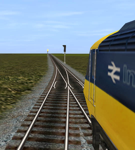
Rename the junction, dust some textures, throw a couple of signals at it...

Regards
Charlie